'Need to Knows' About Pellet Stove Sensors and Controls
Pellet stoves use sensors to monitor and control the pellet stove during all four phases of use, OFF, STARTUP, RUN, and SHUTDOWN. Some sensors are for safety and other sensors are for control, some do both.
 To properly understand their function you must learn some basic nomenclature. Switches turn an electronic signal either “ON” (closed circuit) or “OFF” (open circuit). If the switch is normally open, that means that in its unaffected state, the circuit is “OFF”, if a switch is normally closed, in its unaffected state the circuit is “ON” or it has continuity.
Electric signals in pellet stoves can be either AC (alternating current) or DC (direct current). The power that the signal has is measured in volts, the force of the signal is measured in amps and the resistance a signal has flowing through a wire or component is measured in Ohms.
To test various sensors and controls you will need a handheld, digital multimeter (DMM). While we are not going to tell you how to use the DMM, this tool can be your best friend as it can measure both AC and DC volts, line amps, Ohm resistance, continuity, and a slew of other various measurements.
Pellet Stove Control and Sensor Types
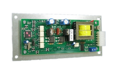
- Stove Control Boards – Most, if not all pellet stoves, use some type of digital controller as the central user interface on the stove. Digital controllers are good for users because they usually have a display that shows what the stove is doing and if a problem arises, can also report the error. Additionally, because digital controls run a series of set programs, many controllers allow the user to fine-tune the stove or input additional information to enhance the stove’s operation. The downside to digital controllers is that they can be susceptible to power surges and can damage easily. For this reason, a surge protector should always be used to protect the controller.
- Pellet Stove Motherboard/ Daughter Board- a configuration of a digital controller where the control board is mounted in one place (motherboard) and is controlled from a different place using another controller (daughter board) connected via a communication cable.
- Pellet Stove Timer Boxes- are used in analog stoves to initiate power to the stove upon closing an electrical contact across the timer, usually using a button or rocker switch. Typically, a timer box will run an internal clock between 15-30 minutes to allow the stove to startup and achieve “proof of fire” via a low limit snap disc. If the sensors detect enough heat to close its contacts, power will be diverted away from the timer box to allow the stove to continue to run. Stoves that use automatic igniters and have timer boxes for the start cycle will cut power to the ignition system when time runs out even though the igniter will also have a limit switch to turn off power while the stove is running. If the fire dies out in the stove, because the user turned off the stove or the stoves runs out of fuel, power is diverted back to the timer box that presumably is now off and ready for the start button to be actuated again for another startup. Stoves that use digital controllers do not need timer boxed because the controller itself is running a clock that can perform all of these functions internally.
- Rheostats and Potentiometers (pots)-are used to restrict the flow of power to a pellet stove’s components. A rheostat can turn AC power “OFF” and “ON” to a motor (usually a room blower) as well as create resistance to the signal, thus controlling the motors speed. Rheostats create resistance to a line voltage AC signal thus limiting its output voltage. A Potentiometer takes an AC line voltage signal and converts it to a correlating low voltage signal much the same way as a rheostat but instead of that signal directly controlling a motor, the signal is passed through another type of control. An example of a potentiometer would be the heat control on analog stoves that controls the feed. The potentiometer takes in line voltage and converts it to a low voltage signal received by a delay timer. This allows users to turn the heat up or down on the stove using a dial which either increases or decreases a delay timer which controls another AC line voltage signal to the feed motor. Potentiometers can have more than one output signal thus allowing one dial control to affect multiple components. For example; the dial-a-fire control on the Enviro EF4 and EF5 (Solus and Evolution), use a double potentiometer to delay the auger timer and reduce the combustion blower voltage simultaneously.
- Delay Timer Boxes- are used on analog stoves to cut the flow of electricity to the feed system at different intervals based upon the selection of a potentiometer. Typically a delay timer will have a programmed amount of time “ON”, usually somewhere between 2 and 4 seconds and based upon a user’s selection on the dial of a potentiometer the “OFF” time of the delay box will be increased or decreased. More delay time means less feed and less heat and less delay time equals more heat and a bigger fire.
- Phase Controllers- are used in analog stoves to reduce the voltage to a motor, usually a combustion blower, using a signal controlled by a potentiometer.
- Micro Switches – are used to turn electrical current on or off to components or to notify the control board of an event. Buttons that depress when hopper lids are closed or open when the door is opened usually are wired directly to the feed system or to the control board to turn off the feed when the switches contacts are opened.
- Thermocouples – are dissimilar metal wires that are joined at the tip (usually copper and steel) to measure temperature. When dissimilar metals touch each other they swap electrons (generate very low amounts of electricity) and by raising or lower the temperature at the tip more or less electricity can be generated, thus allowing an accurate measurement of a temperature. Quadrafire and Heatilator use a thermocouple to measure temperature set points directly over the burn pot to detect “fire-on-rise”, thus enabling the controller to know when the stove is moving out of startup and into run mode. Many other companies use thermocouples to measure exhaust temperatures to do the same thing.
- Thermo-resistor – used like a thermocouple, a thermo-resistor uses a resistor to restrict the continuity (flow of electricity) of a circuit, as heat is increased the flow of electricity is reduced. The main difference between thermocouples and thermos-resistors is; thermocouples generate electricity which is measured and thermos-resistors restrict a generated current.
- Optical Switches – used to detect motion or proximity. Quadrafire uses an optical switch on its Mt Vernon AE stove to verify that the feed motor is spinning at the correct speed. Rika uses an optical switch to monitor air flow into the pellet stove. Optical switches are not very common on stoves.
-
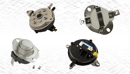
Airflow Sensor/ Vacuum Switch – are used to open or close a circuit when air pressure is either above or below a predefined threshold as noted by the switch. Air pressure is measured in the water column (“WC); which is the amount of pressure it takes to raise or lower water in a 1” diameter tube. In pellet stoves, the combustion blower is responsible for delivering air to the firebox. As the air flows through the stove the air pressure is measured by pushing or sucking the air through a tube and either closing or expanding a rubber diaphragm to open or close a microswitch inside the switch housing. Some airflow switches have one port for the hose to connect and will be dedicated switches that can only open or only close when a defined amount of pressure is gained or lost. These switches will also only have two terminals for wires. Some stoves use differential switches that have two ports for hoses and three terminals for wires. These types of switches can monitor positive or negative pressure and can open or close depending on how they are wired. When the diaphragm closes or expands there are contacts on both sides of the diaphragm to allow for several ways to use the switch.
If the air measurement port of the stove, the place where the air is monitored from is upstream from the blower (located somewhere from the intake and before the blower), the switch will be monitoring negative pressure (vacuum) and the contacts of the switch will be normally open waiting for pressure to close the contacts. If the air flow switch is monitoring the air flow after the combustion blower and before the exhaust, it is going to be a pressure switch and will be normally closed. If the vent is clogged the back pressure will open the switch can cut power to the feed system. Aside from Whitfield (both Pyro Industries and Lennox) and a handful of very old and rare pellet stoves that used a positive pressure switch, nearly all pellet stoves made now will be using vacuum switches seeking negative pressure.
There is an inherent problem with pressure switches that are normally closed; if they fail, you will not know it, which is why most switches now are normally open and seek negative pressure to close it. A common failure, aside from clogged vents or very dirty stoves is a bad combustion blower. When an air flow switch seeks negative pressure to close contacts and the combustion blower isn’t working, the stove cannot start. If an air flow switch is wired backward or if you have an older Whitfield, it’s possible for a stove to start feeding and possibly ignite and smoke will come into the house. - Snap Discs – Used to complete or cut a circuit when a defined temperature is attained or lost. Snap discs come in three variations, F-Type, L-Type and Rollout. An “F” switch is typically called a “Fan” switch and is normally open (no circuit) and closes (completes circuit) when a defined temperature is attained. For example, an F110-20 closes at 110 degrees Fahrenheit and closes at 20 degrees below 110 or 90 degrees.

- Hall Sensors – are electromagnetic sensors used to determine high-speed revolutions per minute (RPM) of a blower motor and are integrated into the blower assembly itself. Monitoring the RPM of the motor may be for display or troubleshooting purposes only within a controller or very sophisticated stoves may actually monitor this for efficiency purposes. Hall sensors can fail even if the blower is actually working and because of this are very difficult to diagnose, especially of the stove uses this information for running purposes.


Comments
Leave a comment